
Architectural Boundaries & Scope Mapping
Why 'Out of Scope' Still Needs a Place on the Diagram
Omitting external systems from architectural diagrams leads to hidden dependencies, unmanaged contracts, and integration surprises. Here is how explicit exclusion creates clarity.
Author: Daniel White
•
Published: September 8, 2026
•
Reading Time: 6 min read

Table of Contents
Navigate through the boundary breakdown sections.
The Fallacy of the Clean Canvas
Why drawing only what you own distorts architectural reality and masks boundary friction.
Software teams often begin architectural modeling by drawing an immaculate boundary box around their immediate deliverables. Everything owned by the team goes inside the box, while adjacent services, shared legacy datastores, and upstream partner APIs are omitted entirely to keep the view uncluttered. This creates a dangerous illusion of complete autonomy.
When an engineering team ignores surrounding systems, they design interfaces against idealized assumptions rather than physical constraints. Critical operational friction points—such as network latency, batch sync windows, throttling limits, and split authentication workflows—vanish from early reviews.
“A diagram that shows only internal components is not a system model; it is an isolated wishlist that hides where ownership transfers.”
Structural Risks of Invisible Neighbors
Omitting external systems creates delivery blind spots that emerge during production integration.
When adjacent services remain invisible on system diagrams, engineers build local solutions that fail at the perimeter. The absence of explicit excluded nodes prevents security teams from verifying transit boundaries and leaves product owners unable to track external blockers.
Primary Hazards of Scope Omission
Systematic omission of out-of-scope elements manifests across three distinct architectural operational risks:
- Contract Ambiguity: Undocumented dependencies assume flexible JSON contracts where rigid legacy RPC schemas actually exist.
- Failure Cascade Neglect: Missing upstream proxies prevent developers from designing proper circuit breakers and retry buffers.
- Boundary Creep: Ambiguous borders invite unplanned feature creep into internal services when external teams refuse to build interface adapters.
Key Facts & Parameters
System topology matrices and interface constraints for reference.
| Dimension / Scope Parameter | Designation / Standard |
|---|---|
| Scope Demarcation Standard | Faded Box with Dashed Perimeter (30% Opacity) |
| Ingress / Egress Labeling | Explicit Protocol & Rate Constraints on Crossing Edges |
| Ownership Metadata | External Team Alias & Escalation Channel Annotation |
| Architecture Review Requirement | Mandatory Inclusion of Level-1 Adjacent Services |
Visual Grammar for Out-of-Scope Elements
Rendering excluded entities without cluttering the primary operational flow.
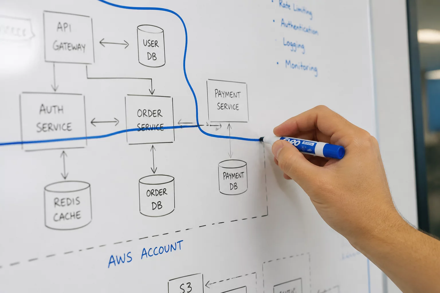
Effective system diagrams employ a strict visual syntax to differentiate active scope from contextual surroundings. Using subdued gray fills, dashed stroke perimeters, and clear boundary markers allows readers to immediately recognize what is outside the team's operational purview while keeping dependency vectors explicit.
Every edge crossing the system boundary must carry explicit data transfer annotations. Indicating protocol types, payload frequencies, and ownership contacts on the connecting arrows transforms a passive diagram into an active integration agreement between collaborating departments.
Governance & Team Alignment Tactics
Practical patterns to maintain clear boundary distinctions during iterative development cycles.
Maintaining up-to-date boundary models requires disciplined engineering habits during sprint planning and architecture syncs. Diagrams should be reviewed whenever upstream dependencies introduce breaking version bumps or modified rate limits.
Implementation Checklist
- Render all Level-1 external consumers and upstream providers as dashed, desaturated blocks around your primary system boundary.
- Annotate every boundary-crossing connector with protocol name, synchronous or asynchronous behavior, and payload ownership.
- Review external dependencies quarterly to detect obsolete integration points or stealth boundary shifts.
Fieldbook Dispatch
Subscribe to System Boundary Analysis Memos
Receive regular architectural pattern updates, scope checklists, and engineering case studies directly in your inbox.
Knowledge Base Archive
Related Boundary Studies


DW
Domain Specialist
Daniel White
Daniel White is a Principal Systems Architect specializing in distributed system boundaries, domain-driven design, and cross-team integration modeling for enterprise engineering teams.