
Knowledge Base
When a Box Around Everything Explains Nothing
Enclosing heterogeneous subsystems inside a single monolithic diagram boundary creates an illusion of simplicity while hiding operational blast radiuses, ownership ambiguity, and external communication vectors.
Author: Ashley Thompson
•
Published: August 20, 2026
•
Reading Time: 7 min read

Table of Contents
Navigate through the boundary breakdown sections.
The Illusion of the All-Encompassing Container
Drawing a single broad boundary across legacy services, external APIs, and modern microservices gives stakeholders a false sense of cohesion.
Architectural diagrams frequently break down when engineers attempt to convey simplicity by drawing one gigantic rectangular container around diverse software components. When distinct applications sit inside the exact same perimeter without clear internal divisions, teams cannot differentiate between rapid in-memory interactions and latency-prone external network calls. This monolithic grouping obscures critical operational frictions that teams need to evaluate during system planning.
A boundary must define an explicit operational enforcement zone where access controls, deployment cycles, data governance, and service level agreements transition. When a diagram bundles identity brokers, message brokers, billing integrations, and reporting pipelines into a single undifferentiated block, the diagram stops functioning as an engineering blueprint.
A boundary that includes every moving part without demarcating responsibility does not clarify system architecture—it merely documents physical proximity inside a single viewport.
Failure Modes of Monolithic Boundary Grouping
When boundaries fail to reflect operational reality, cross-team collaboration breaks down across multiple architectural dimensions.
Masking complex internal interactions behind an overly generalized container produces critical blind spots during system incidents and refactoring initiatives.
Primary Symptoms of Undifferentiated System Boundaries
Engineering organizations that rely on vague, all-in-one boundaries frequently experience predictable friction across their deployment lifecycles:
- Ambiguous Incident Ownership: During major production incidents, engineers struggle to identify the responsible squad because the master diagram presents all subsystems under shared stewardship.
- Unseen Cascading Failures: Unmapped synchronous dependencies between components inside the box cause cluster-wide outages when one auxiliary service degrades.
- Security Perimeter Degradation: Treating everything inside the master container as an internal trusted network encourages unauthenticated service calls and loose access control.
Key Facts & Parameters
System topology matrices and interface constraints for reference.
| Dimension / Scope Parameter | Designation / Standard |
|---|---|
| Viewport Component Density | 3 to 7 discrete subsystems per bounded diagram layer |
| Interface Protocol Definition | Explicit protocol (gRPC / HTTPS / Async Event) at every boundary crossing |
| Ownership Alignment | Strict 1:1 relationship between bounded container and responsible team |
| Failure Domain Isolation | Explicit circuit breaker and fallback policies defined at each perimeter |
Decomposing Boundaries into Functional Zones
Converting an uninformative master box into clear responsibility zones requires layering context, deployment scopes, and trust perimeters.
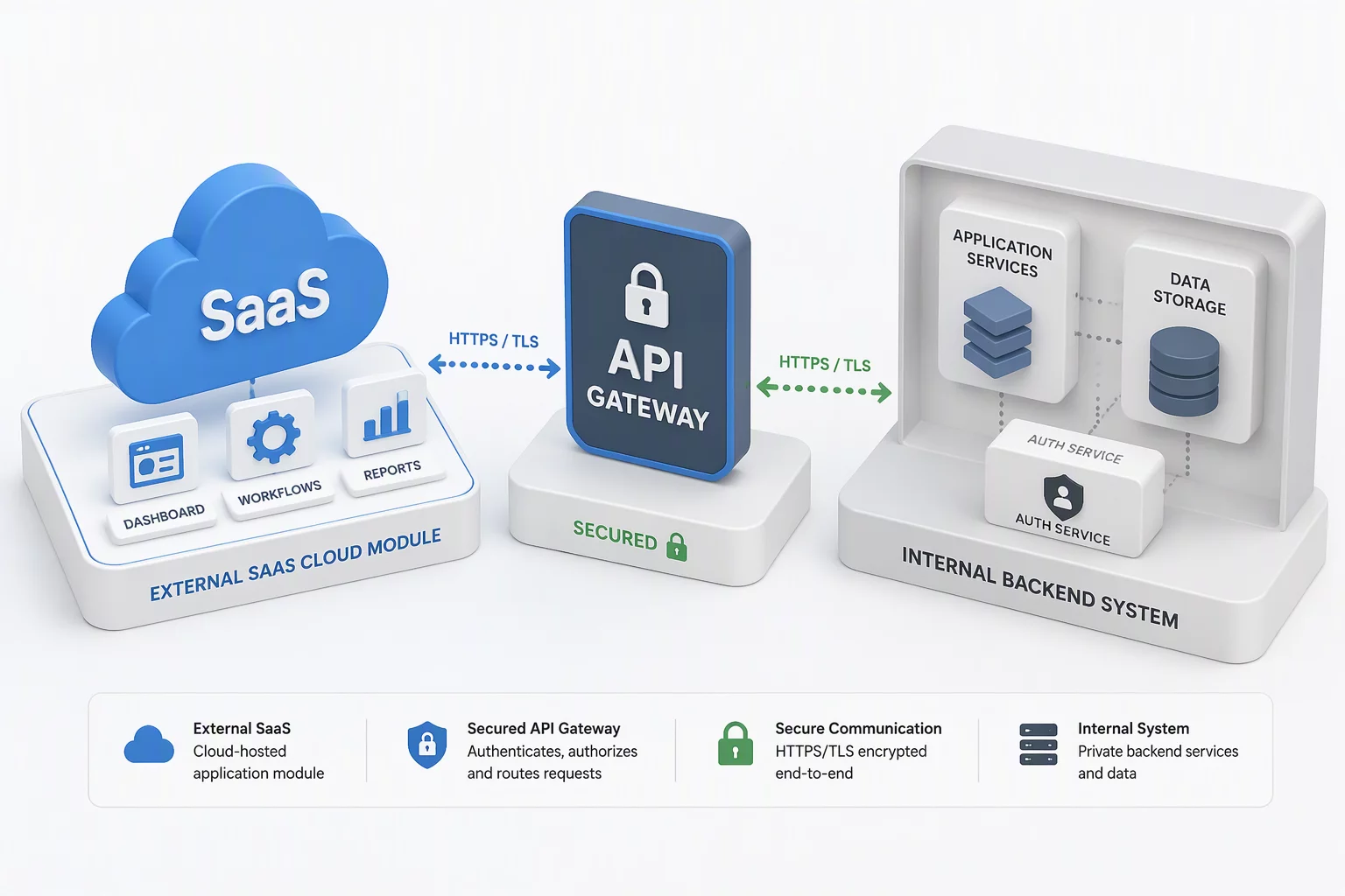
Effective system modeling starts by partitioning the diagram into autonomous capability domains. Instead of drawing a single encompassing container, architects should establish nested, clearly defined boundaries: a Context Boundary representing business domain scope, a Deployment Boundary illustrating runtime infrastructure, and a Security Perimeter isolating protected datastores and credentials.
Every connection line that traverses from one functional zone into another must explicitly designate the transport protocol, data schema, and authorization mechanism. When boundary transitions follow formal specifications, engineers can independently evolve internal modules without triggering unexpected cross-boundary regressions.
Pragmatic Architecture Remediation Protocol
Follow this step-by-step checklist to refactor uninformative system boxes into actionable architectural diagrams.
Systematic remediation of legacy diagrams ensures that architectural reviews, onboarding roadmaps, and threat assessments reflect genuine runtime mechanics rather than convenient simplifications.
Implementation Checklist
- Audit legacy system diagrams to dismantle all generic boxes containing more than one distinct domain model or team ownership group.
- Label every boundary-crossing connector with its exact transport protocol, failure timeout, and authentication schema.
- Designate explicit engineering ownership and escalation matrices for each newly isolated perimeter.
Fieldbook Dispatch
Subscribe to System Boundary Analysis Memos
Receive regular architectural pattern updates, scope checklists, and engineering case studies directly in your inbox.
Knowledge Base Archive
Related Boundary Studies

AT
Domain Specialist
Ashley Thompson
Senior Systems Architect and BoundaryFrame contributor specializing in distributed systems topology, domain boundary modeling, and enterprise microservice governance frameworks.